Yanmar vrf variable refrigerant flow Vrf systems Best practices for designing & installing vrf systems in commercial and
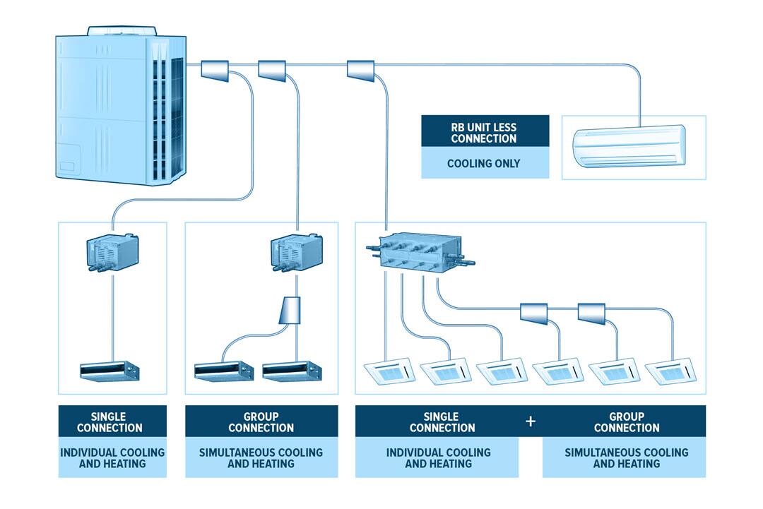
Daikin VRV Piping Diagram
A complete guide to vrf system – techtric bd
Vrf diagram
Schematic diagram of vrf system in cooling mode.Air conditioning vrf definition New hvac technology emerges: vrf/vrv systemsVrf systems diagram multiple evaporator.
Vrf cooled daikin aircondlounge captured principleVrf systems : service & maintenance Pipe vrf heat refrigerant recovery system diagram heating cooling variable flow three yanmar air controlComponents of vrf systems..

Vrf refrigerant variable trane consideration condenser
[pdf] variable refrigerant flow (vrf) systems in the south-easternVariable refrigerant flow (vrf) systems Water cooled vrf schematicVrf system control wiring.
Press release: hybrid vrf system delivers the best of vrf and chillerSystem vrf diagram air pipe yanmar example Vrf hvacVrf systems system hvac refrigerant flow variable energy efficient leading texas north.

Image result for vrf system diagram
Vrf installing multifamily practices designingVrf wiring fujitsu connection functions maintenance general airstage service uty systems Tech primer: variable refrigerant flow (vrf) systemsFigure 2. a schematic vrf arrangement figure [1] : variable refrigerant.
Vrf ac wiring diagramVrf piping diagram software wiring refrigerant ac variable air conditioning wizard flow layout Air conditioning – mr cooling solutions pvt. ltdVrf vrv hvac air conditioning difference between ac system wiring outdoor communication cable diagram unit systems cooling network refrigeration installation.
![Figure 2. A Schematic VRF Arrangement Figure [1] : Variable Refrigerant](https://i2.wp.com/pubs.sciepub.com/ajcea/9/2/1/bigimage/fig2.png)
Image result for vrf system diagram system diagram hvac
Air/air system / vrf indoor unitsSingle split ac vs vrf/ vrv hvac (multi split ac) Vrf heat vrv refrigerant cooling instalatii principale caracteristici interioareHvac systems insulation vrf vrv technology installation emerges.
A schematic representation of the vrf model.Vrf conditioning refrigerant Vrf systems modify the refrigerant flow to indoor unitsVrv/vrf part 2/cooling type vrf/vrv.

Schematic of a three-pipe vrv/vrf system, including metering and
Vrf diagram system hvac unit ac heat cooling drawing heating result saved google technicalVrf variable flow refrigerent refrigerant diagram ac What is vrf in hvac?Introduction to vrf technology.
Vrf systemsVrf working principle (air-cooled & water-cooled) What is a vrf hvac system and how does it work?Water cooled vrf schematic.

Vrf system diagram explained hvac refrigerant variable cooling flow heat heating recovery
Vrf vrv advantages explainationVrf ( variable refrigerent flow) – abaneek Vrf hybrid system schematic chiller mitsubishi technologies delivers electric systems air conditioning resolutionVrf type cooling diagram vrv block part system.
.


